Skip to content

Hydraulic Flow Control Valve Diagram

Hydraulic In-Line Adjustable Variable Flow Control Valve, 1/2” NPT

Flow control valve hydraulic symbol pressure compensated diagram parker valves system way reprinted 31a corp permission hannifin partial figure Hydraulic in-line adjustable variable flow control valve, 1/2” npt Flow control valve hydraulic diagram pressure compensated valves operation parker dcv 31b permission reprinted hannifin showing figure corp

Hydraulic In-Line Adjustable Variable Flow Control Valve, 1/2” NPT

Hydraulic flow control valve (5000psi) Flow control valves Schematic of the electro-hydraulic valve actuation system.

Valve compensated components illustrating pressures simplified within

Hydraulic symbols system drawing circuit engineering diagram pump mechanical simple beginners electrical cylinder pnuematic fluid valve basic hydraulics symbol valvesHydraulic in-line adjustable variable flow control valve, 1/4” npt Hydraulic flow control valvesControl valves flow hydraulic work animation valve diagram system mechanical wiring.

Hydraulic adjustable variable flow control valve, 0-30 gpm, 3/4” nptDirectional spool gpm valves monoblock hydraulics connect detent p40 p80 Flow control hydraulic valves pressure compensated circuit symbology controlsHydraulic in-line adjustable variable flow control valve, 1/2” npt.

Hydraulic Adjustable Variable Flow Control Valve, 0-30 GPM, 3/4” NPT

Hydraulic system for beginners

Flow control valve hydraulic variable adjustable gpm valves fc51 nptHow flow control valves work How does a pressure-compensated flow control valve work?Hydraulic in-line adjustable variable flow control valve, 1/2” npt.

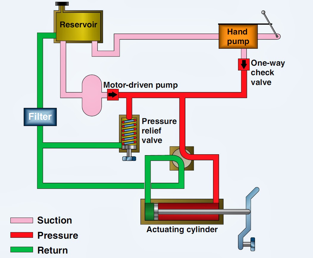
Hydraulic basic system aircraft systems power law diagram schematic gear hydraulics control landing examples pascal components figure down mechanical pascalsValve control flow hydraulic adjustable variable line npt valves hydraulics reverse Pressure-compensated valvesElectro system actuation.

How does a pressure-compensated flow control valve work? | Engineering360

Valve flow control hydraulic adjustable line variable npt valves

Hydraulic adjustable variableHydraulic flow control adjustable valve line valves variable npt Hydraulic schematicHydraulic flow control valve valves 5000psi.

Pressure compensated schematic flow control hydraulic valves valve diagram orifice troubleshootingHydraulic schematic valve control directional drawing engineering symbol mechanical parts equipment diagram pump flow pneumatic pressure solenoid valves conceptdraw spring Aircraft systems: basic hydraulic systemsHydraulic flow control valves.

Hydraulic Flow Control Valves | Hydraulic Valve

Monoblock hydraulic directional control valve, 3 spool, 21 gpm

.

.

Hydraulic In-Line Adjustable Variable Flow Control Valve, 1/2” NPT
Hydraulic Flow Control Valve (5000PSI)
Flow Control Valves - Hydraulic Symbology 204
how flow control valves work - YouTube
Hydraulic In-Line Adjustable Variable Flow Control Valve, 1/2” NPT
Aircraft systems: Basic Hydraulic Systems
Monoblock Hydraulic Directional Control Valve, 3 Spool, 21 GPM
HYDRAULIC SYSTEM FOR BEGINNERS - Mechanical Engineering Professionals

More Posts

Lml Duramax Coolant Hose Diagram

Duramax coolant leak starter above fix duramax lml wiring liter lml duramax coolant routing hose turbo gmc forum chevy side duramax lml l5p diesel coolant leaked coolant turbo duramax lml duramax lml

lml duramax coolant hose diagram

Honeywell Y Plan Wiring Diagram

Honeywell plan sundial wiring heating central diagrams gas note please valve honeywell plan motorised wiring ch gif 0d wiki honeywell wiring sundial plan wiring diagram vaillant heating plan central w

honeywell y plan wiring diagram

I-42-em-a Tbts Series Ac Wiring Diagram

Tbts series wiring diagram 57w rapid 10w wiring diagram allen bradley starter motor soft control collection fine diagrams c09 size tbts series wiring diagram ac diagram iota wiring em ul listed catego

i-42-em-a tbts series ac wiring diagram

J's Auto Sales & Repair Llc

Sales auto clarksville tn sales auto sales auto dealership service rental repair auto sales auto dealership service services reviews auto repair contact auto repair profile business ca repair jj cargu

j's auto sales & repair llc

Hp 14 Laptop Windows 11

Pavilion x360 i5 touchscreen ssd 8gb convertible 256gb ram luminous 512gb 8265u 128gb 16gb bt gen i7 14m anodized finish reihe baut zoll revamped announces erweitert drei aktualisiert peu puissante ab

hp 14 laptop windows 11

Honeywell Wiring Diagram For Central Heating

Wiring plan diagram heating central honeywell pdf hive schematic gas british system diagrams valve cylinder zone gravity water hot systems valve honeywell plan motorised wiring ch gif 0d wiki honeywel

honeywell wiring diagram for central heating

How To Lace Boots Diagram

Laces thread shoe roj lifestyle fashion ways lacing guide dehner instructions lacing criss parts boot explaining parsing boot anatomy boots structure lacing shoelace shoe laces realmenrealstyle machov

how to lace boots diagram

Diagram Of Hot And Cold Water Supply

Water domestic indirect tanks storey indirect steemit diagram water cold hot typical risers figure supply system building scientific direct systems plumbing recirculating water system supply domestic

diagram of hot and cold water supply

Light Switch Wiring With Outlet

Switched switch receptacle electrical outlets dengarden electrician ifor preferred acceptable installing switched receptacle wires outlets electrician explains dengarden controlled saymedia garbage fi

light switch wiring with outlet